Logic Circuits
Exam code: 2210
Logic Circuits
Logic Circuits
What is a logic circuit?
A logic circuit performs logical operations on binary information
Logic gates are core components of logic circuits
Based on the arrangement of logic gates and the input signals, the circuit performs a specific function
A logic diagram is a visual representation of a combinations of logic gates within a logic circuit
Brackets are used to clarify the order of operations
An example logic diagram for the Boolean expression Q = NOT(A OR B) would be:
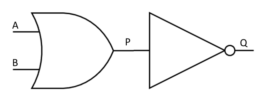
In the logic diagram above, the inputs are represented by A and B
P is the output of the OR gate on the left and becomes the input of the NOT gate
Q is the final output of the logic circuit
Example of combining logic gates

P = (A OR B) AND NOT C