Truth Tables
Truth Tables
Truth Tables
What is a truth table?
A truth table is a tool used in logic and computer science to visualise the results of Boolean expressions
They represent all possible inputs and the associated outputs for a given Boolean expression
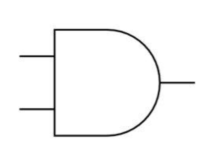
AND
Circuit symbol | Truth Table | |||||||||||||||
|---|---|---|---|---|---|---|---|---|---|---|---|---|---|---|---|---|
 |
|
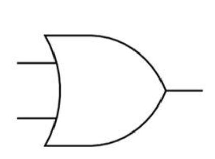
OR
Circuit symbol | Truth Table | |||||||||||||||
|---|---|---|---|---|---|---|---|---|---|---|---|---|---|---|---|---|
 |
|
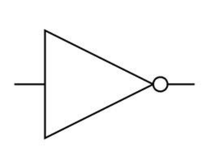
NOT
Circuit symbol | Truth Table | ||||||
|---|---|---|---|---|---|---|---|
 |
|
XOR (exclusive)
Circuit symbol | Truth Table | |||||||||||||||
|---|---|---|---|---|---|---|---|---|---|---|---|---|---|---|---|---|
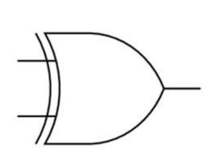 |
|
NAND (not and)
Circuit symbol | Truth Table | |||||||||||||||
|---|---|---|---|---|---|---|---|---|---|---|---|---|---|---|---|---|
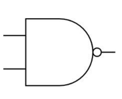 |
|
NOR (not or)
Circuit symbol | Truth Table | |||||||||||||||
|---|---|---|---|---|---|---|---|---|---|---|---|---|---|---|---|---|
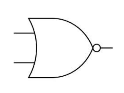 |
|
Truth Tables for Logic Circuits
Truth Tables for Logic Circuits
How do you create truth tables for logic circuits?
To create a truth table for the expression P = (A AND B) AND NOT C
Calculate the numbers of rows needed (2number of inputs)
In this example there are 3 inputs (A, B, C) so a total of 8 rows are needed (23)
To not miss any combination of inputs, start with 000 and count up in 3-bit binary (0-7)
A | B | C |
|---|---|---|
0 | 0 | 0 |
0 | 0 | 1 |
0 | 1 | 0 |
0 | 1 | 1 |
1 | 0 | 0 |
1 | 0 | 1 |
1 | 1 | 0 |
1 | 1 | 1 |
Add a new column to show the results of the brackets first (A AND B)
A | B | C | A AND B |
|---|---|---|---|
0 | 0 | 0 | 0 |
0 | 0 | 1 | 0 |
0 | 1 | 0 | 0 |
0 | 1 | 1 | 0 |
1 | 0 | 0 | 0 |
1 | 0 | 1 | 0 |
1 | 1 | 0 | 1 |
1 | 1 | 1 | 1 |
Add a new column to show the results of NOT C
A | B | C | A AND B | NOT C |
|---|---|---|---|---|
0 | 0 | 0 | 0 | 1 |
0 | 0 | 1 | 0 | 0 |
0 | 1 | 0 | 0 | 1 |
0 | 1 | 1 | 0 | 0 |
1 | 0 | 0 | 0 | 1 |
1 | 0 | 1 | 0 | 0 |
1 | 1 | 0 | 1 | 1 |
1 | 1 | 1 | 1 | 0 |
The last column shows the result of the Boolean expression (P) by comparing (A AND B) AND NOT C //
A | B | C | A AND B | NOT C | P |
|---|---|---|---|---|---|
0 | 0 | 0 | 0 | 1 | 0 |
0 | 0 | 1 | 0 | 0 | 0 |
0 | 1 | 0 | 0 | 1 | 0 |
0 | 1 | 1 | 0 | 0 | 0 |
1 | 0 | 0 | 0 | 1 | 0 |
1 | 0 | 1 | 0 | 0 | 0 |
1 | 1 | 0 | 1 | 1 | 1 |
1 | 1 | 1 | 1 | 0 | 0 |
How do you create logic circuits from a truth table?
To create a logic circuit from a truth table you need to:
Find the rows where the output = 1
Build a logic branch for each of the rows
Combine the branches
Determine the gates needed
Construct a logic expression
Create the logic circuit
Example
A | B | C | X |
|---|---|---|---|
0 | 0 | 0 | 0 |
0 | 0 | 1 | 0 |
0 | 1 | 0 | 0 |
0 | 1 | 1 | 0 |
|
|
|
|
1 | 0 | 1 | 0 |
1 | 1 | 0 | 0 |
|
|
|
|
Look at the truth table and find the rows where X = 1
This happens when:
A = 1, B = 0, C = 0
A = 1, B = 1, C = 1
Build a logic branch:
A = 1, B = 0, C = 0
Use a NOT gate on B
Use a NOT gate on C
AND A, NOT B, and NOT C together
This gives output = 1 for that row
A = 1, B = 1, C = 1
Just AND A, B, and C together
Combine the branches
Use an OR gate to combine the two outputs
This way, X = 1 if either input combination happens
Determine the gates needed:
NOT gates:
NOT B
NOT C
AND gates:
A AND NOT B → first AND
that result AND NOT C → second AND
A AND B → third AND
that result AND C → fourth AND
OR gate:
Combines the outputs of the second and fourth AND gates
Construct the logic expression
Final logic:
(A AND NOT B AND NOT C) OR (A AND B AND C)
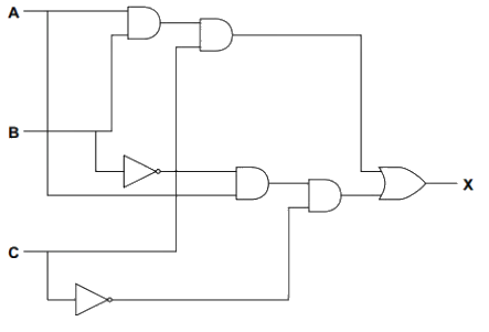
Create the logic circuit