Electromotive Force & Potential Difference
Electromotive Force
Electromotive Force
The electromotive Force (e.m.f.) is the name given to the potential difference of the power source in a circuit
It is defined as
The electrical work done by a source in moving a unit charge around a complete circuit
Electromotive force (e.m.f.) is measured in volts (V)
Electromotive Force in a Circuit
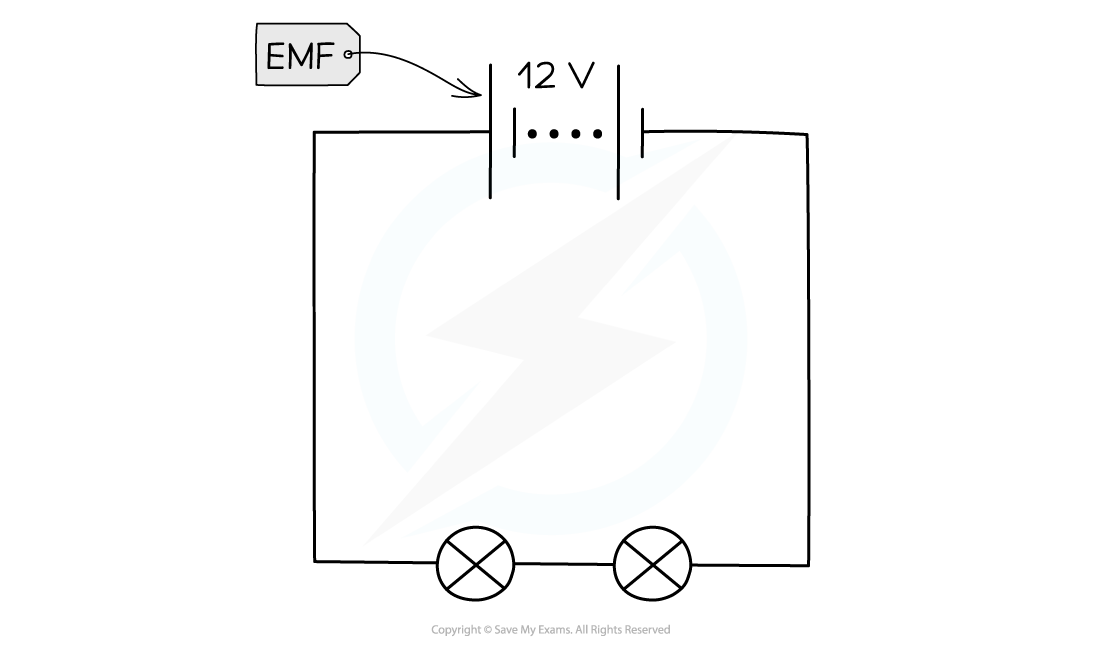
The EMF is the voltage supplied by a power supply: 12 V in the above case
The definition of e.m.f. can also be expressed using an equation
Where
E = electromotive force (e.m.f.) (V)
W = energy supplied to the charges from the power source (J)
Q = charge on each charge carrier (C) Note: in circuits the charge carriers are electrons
This equation should be compared to the definition of potential difference (below) as the two are closely related
Potential Difference
Potential Difference
As charge flows around a circuit energy is transferred from the power source to the charge carriers, and then to the components
This is what makes components such as bulbs light up
The potential difference between two points in a circuit is related to the amount of energy transferred between those points in the circuit
Potential difference is defined as
The work done by a unit charge passing through a component
Potential difference is measure in volts (V)
Electromotive Force and Potential Difference in a Circuit
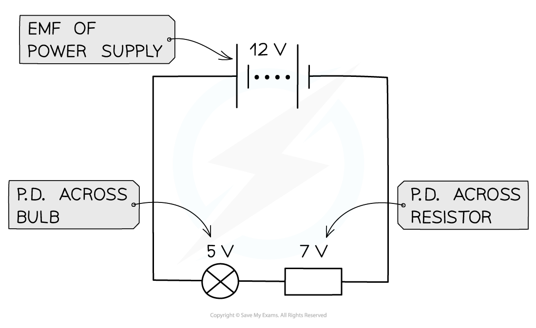
The potential difference is the difference in the electrical potential across each component: 5 volts for the bulb (on the left) and 7 volts for the resistor (on the right)
The definition of p.d. can also be expressed using an equation
Where
V = potential difference (p.d.) (V)
W = energy transferred to the components from the charge carriers (J)
Q = charge on each charge carrier (C)
In circuits the charge carriers are electrons
This equation should be compared to the definition of e.m.f. as the two are closely related due to conservation of energy
Measuring Potential Difference
Measuring Potential Difference
Potential difference is measured using a voltmeter, which can be either
Digital (with an electronic read out)
Analogue (with a needle and scale)
Voltmeters are connected in parallel with the component being tested
The potential difference is the difference in electrical potential between two points, therefore the voltmeter has to be connected to two points in the circuit
Analogue or Digital?
Analogue voltmeters are subject to parallax error
Always read the meter from a position directly perpendicular to the scale
Typical ranges are 0.1-1.0 V and 0-5.0 V for analogue voltmeters although they can vary
Always double check exactly where the marker is before an experiment, if not at zero, you will need to subtract this from all your measurements
They should be checked for zero errors before using
Analogue and Digital Voltmeters

Voltmeters can be either analogue (with a scale and needle) or digital (with electronic read-out)
Digital voltmeters can measure very small potential differences, in mV or µV
Digital displays show the measured values as digits and are more accurate than analogue displays
They’re easy to use because they give a specific value and are capable of displaying more precise values
However digital displays may 'flicker' back and forth between values and a judgement must be made as to which to write down
Digital voltmeters should be checked for zero error
Make sure the reading is zero before starting an experiment, or subtract the “zero” value from the end results
Position of a Voltmeter in a Circuit

Voltmeters are connected in parallel to the component being tested
Calculating Total EMF
Calculating Total EMF
When several cells are connected together in series, their combined EMF is equal to the sum of their individual EMFs
Total Electromotive Force
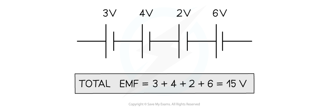
The total EMF of these cells is equal to the sum of their individual EMFs
Potential Difference in Series Circuits
In a series circuit, the sum of potential differences across the components is equal to the total EMF of the power supply
Potential Difference in Series

In a series circuit the components share the EMF of the power supply
Potential Difference in Parallel Circuits
A parallel circuit consists of two or more components attached along separate branches of the circuit
Parallel Circuit
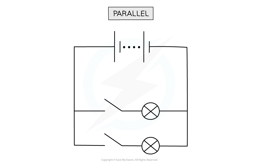
Diagram showing two bulbs connected in parallel
The advantages of this kind of circuit are:
The components can be individually controlled, using their own switches
If one component stops working the others will continue to function
In a parallel circuit, the current splits up - some of it going one way and the rest going the other
This means that the current in each branch will be smaller than the current from the power supply