Resistance of a Wire
Proportionality Relationships for Electrical Conductors
Proportionality Relationships for Electrical Conductors
The relationship between resistance, length and cross-sectional area can be represented mathematically
Resistance is directly proportional to length
Resistance is inversely proportional to cross-sectional area (width, or thickness)
Proportional Relationships Between Resistance, Length & Cross-Sectional Area
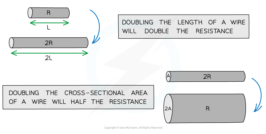
Resistance is directly proportional to the length of the wire and indirectly proportional to the cross-sectional area
I-V Graphs for Ohmic Resistors, Filament Lamps & Diodes
I-V Graphs for Ohmic Resistors, Filament Lamps & Diodes
As the potential difference (voltage) across a component is increased, the current in the component also increases
The precise relationship between voltage and current can be different for different types of components and is shown by an IV graph:
IV Graphs for a Resistor & a Filament Lamp
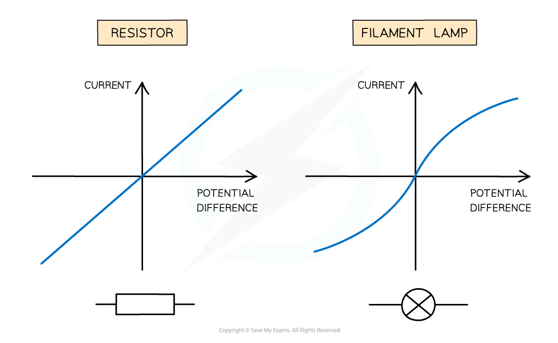
The IV graph for a resistor is a straight line through the origin, the resistance for a filament lamp changes with temperature
The IV graph for a resistor is very simple:
The current is proportional to the potential difference
This is because the resistor has a constant resistance
For a lamp the relationship is more complicated:
The current increases at a proportionally slower rate than the potential difference
This is because:
The current causes the filament in the lamp to heat up
As the filament gets hot, its resistance increases
This opposes the current, causing it to increase at a slower rate
Effect of Temperature on Resistance
Effect of Temperature on Resistance
The resistivity of a thermistor behaves in the opposite way to metals
This is because it is a type of semiconductor
Semiconductors behave in a different way to metals
The number density of charge carriers (such as electrons) increases with increasing temperature
Therefore, for a thermistor:
An increase in temperature causes a decrease in resistance and resistivity
A decrease in temperature causes an increase in resistance and resistivity
Thermistors are often used in temperature sensing circuits such as thermometers and thermostats
A thermistor is a non-ohmic conductor and sensory resistor whose resistance varies with temperature
Most thermistors are negative temperature coefficient ntc) components.
This means that if the temperature increases, the resistance of the thermistor decreases (and vice versa)
Resistance-Temperature Graph for a Thermistor
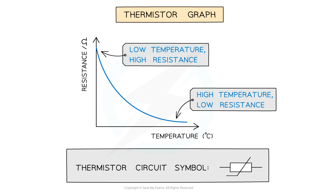
Resistance decreases as temperature increases for a thermistor
Thermistors are temperature sensors and are used in circuits in ovens, fire alarms and digital thermometers
As the thermistor gets hotter, its resistance decreases
As the thermistor gets cooler, its resistance increases
Effect of Temperature on a Thermistor
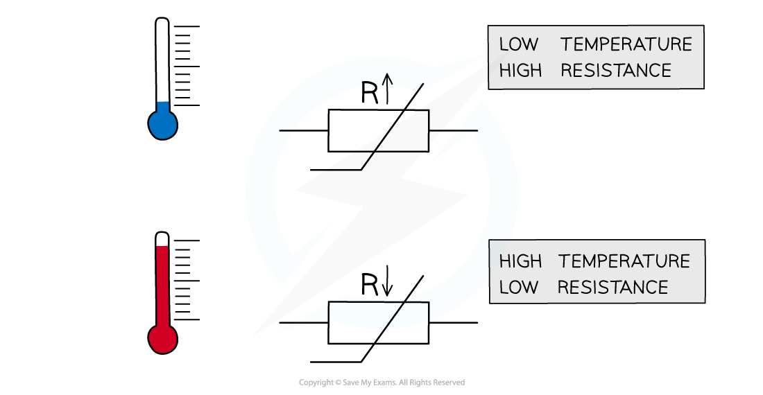
A thermistor has a high resistance at low temperatures and a low resistance at high temperatures