Fields Around Parallel Conductors
Fields Around Parallel Wires
Fields Around Parallel Wires
A current carrying conductor, such as a wire, produces a magnetic field around it
The direction of the field depends on the direction of the current through the wire
This is determined by the right hand thumb rule
Parallel current-carrying conductors will therefore either attract or repel each other
If the currents are in the same direction in both conductors, the magnetic field lines between the conductors cancel out – the conductors will attract each other
If the currents are in the opposite direction in both conductors, the magnetic field lines between the conductors push each other apart – the conductors will repel each other
Repulsion & Attraction of Current-Carrying Wires
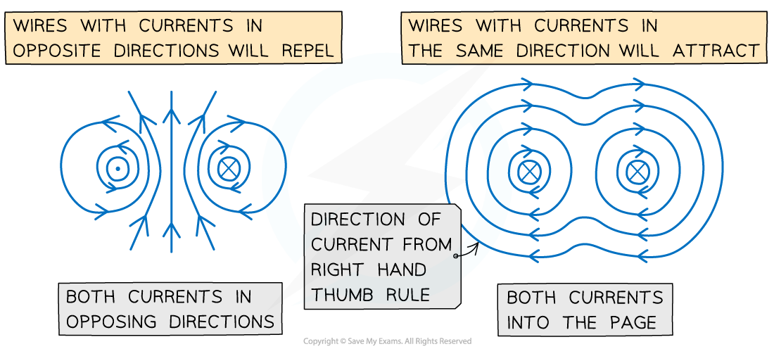
Both wires will attract if their currents are in the same direction and repel if in opposite directions
When the conductors attract, the direction of the magnetic forces will be towards each other
When the conductors repel, the direction of the magnetic forces will be away from each other
The magnitude of each force depends on the amount of current and the length of the wire
Force per Unit Length Between Two Parallel Conductors
is the force per unit length between two parallel currents I1 and I2 separated by a distance r
The force is attractive if the currents are in the same direction and repulsive if they are in opposite directions
It is calculated using the equation:
Where:
F is the force applied between the two parallel wires (N)
L is the length of each parallel conductor (m)
μ0 is the constant for the magnetic permeability of free space = 4π × 10−7 N A−2
I1 is the current through the first conducting wire (A)
I2 is the current through the second conducting wire (A)
r is the separation between the two conducting wires (m)
Forces on Current-Carrying Wires
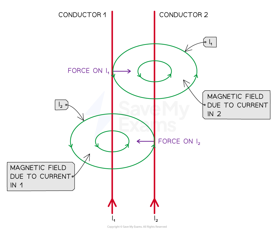
The forces on each of the current-carrying wires are equal and opposite in direction
Obtaining the Equation
The force from wire 2 on wire 1, F2 = B2I1Lsin(θ)
In this situation the magnetic field is perpendicular to the current in the wire, so sin(θ) = 1
F2 = −F1 so the force between them is F
The force on a unit length of the wires is then given by
Hence,
The magnitude of the magnetic field at a radial distance, r away from the current conducting wire is:
In this case the magnetic field strength from B2 at a distance r away from wire 2 is:
Substituting for B2 into the force per unit length equation gives us: